
diff options
| author | Dmitry V. Sokolov <ssloy@users.noreply.github.com> | 2020-02-19 18:10:57 +0300 |
|---|---|---|
| committer | GitHub <noreply@github.com> | 2020-02-19 18:10:57 +0300 |
| commit | d46e3bbf10338b1baaf4e37552151e060f2d3c0a (patch) | |
| tree | e48cb95b2e00ca30a0d480467de1909d17611756 | |
| parent | 1fea37d22cf940a8c8fc13e31fa0f5ca9b718e4c (diff) | |
Update README.md
| -rw-r--r-- | README.md | 10 |
1 files changed, 5 insertions, 5 deletions
@@ -46,6 +46,7 @@ Personally I have locked the thread with a soldering iron: 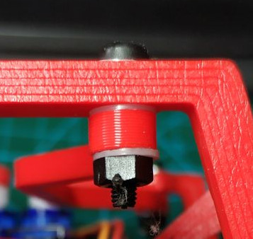 ## The motherboard +### The brain The motherboard itself is pretty basic. It has an ATMega8 microcontroller and the proximity sensor circuit, nothing else. Here is the brain: 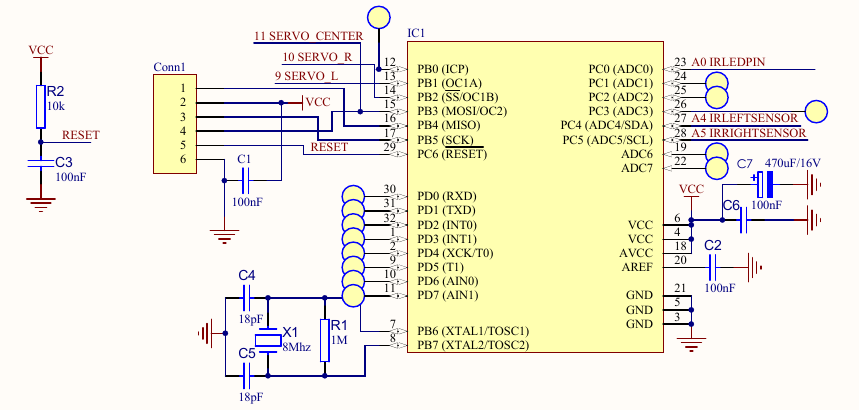 @@ -54,7 +55,6 @@ I recommend soldering the bare minimum to power up the processor, and to flash i 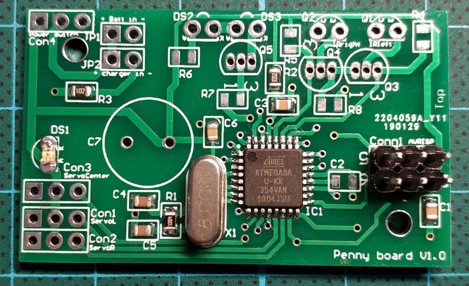 - ### The proximity sensor Penny has two eyes, each one is composed of an infrared LED and a corresponding phototransistor. The LED emits infrared light; this light propagates through the air and once it hits an object it is reflected back towards the phototransistor. @@ -98,7 +98,7 @@ Penny can be programmed via arduino environment, but I find it quite obscure for * [gait sequences](https://github.com/ssloy/penny#gait-sequences) * [obstacle avoidance strategy](https://github.com/ssloy/penny#obstacle-detection) -## PWM generation +### PWM generation The servos take a 50 Hz PWM signal; 1 ms minimum pulse width (0 deg), 2 ms maximum pulse width (90 deg). Penny has three servos, two of them are attached to a 16 bit timer (timer1), and the third one to a 8 bit timer (timer2). If I am not mistaken, arduino's Servo.h controls servomotors via software PWM, and I dislike that, therefore both timers are ticking in fast PWM mode. The microcontroller ticks at 8 MHz, and the timer1 ticks at 1 MHz (prescaler 8), and ICR1 provides the TOP value (20000), thus it restarts every 20 ms, providing a correct 50 Hz signal. OCR1A and OCR1B registers control microsecond pulse widths for the left and right servos. @@ -114,7 +114,7 @@ OCR1A = 1500; // left servo OCR1B = 1500; // right servo OCR2 = 1500/16; // center servo ``` -## Movement planner +### Movement planner First of all, there are 6 important constants in the code: ```c @@ -135,13 +135,13 @@ All the movements are planned as constant speed. To give an example, let us supp Then in an endless loop I invoke `movement_planner()`, it sets the goal `pos[]` according to the plan, and `update_servo_timers()` to update the PWM generator according to the `pos[]` position. -## Gait sequences +### Gait sequences Note that all movement planner variables are stored in 3-element arrays, thus the movements (including the speeds) can be independent one from another. Despite that, my current gait implementation uses synchronized movements of all three servos. -## Obstacle detection +### Obstacle detection |