
diff options
| author | Dmitry V. Sokolov <ssloy@users.noreply.github.com> | 2020-02-19 16:03:17 +0300 |
|---|---|---|
| committer | GitHub <noreply@github.com> | 2020-02-19 16:03:17 +0300 |
| commit | f941bcf81475ed0b499fd2910ac0f9379858e079 (patch) | |
| tree | 35c93db052738e53fb52aef1f9ac345ed042ae0a | |
| parent | 1f669a13c5150790ba7205953b2dd4f4cf142a44 (diff) | |
Update README.md
| -rw-r--r-- | README.md | 45 |
1 files changed, 23 insertions, 22 deletions
@@ -1,5 +1,4 @@ # Meet Penny#3, a 3 servo hexapod. - Penny is a low budget (roughly ten bucks) hexapod. It can be a great one-weekend project to entertain yourself and your kids. Check for Penny dancing to funky music (clickable): [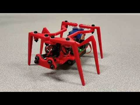](https://youtu.be/quMe5CEoOok) @@ -46,10 +45,8 @@ Personally I have locked the thread with a soldering iron: 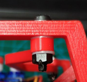 - ## The motherboard - -The motherboard is pretty basic. It has an ATMega8 mcu and the proximity sensor circuit, nothing else. Here is the brain: +The motherboard itself is pretty basic. It has an ATMega8 microcontroller and the proximity sensor circuit, nothing else. Here is the brain: 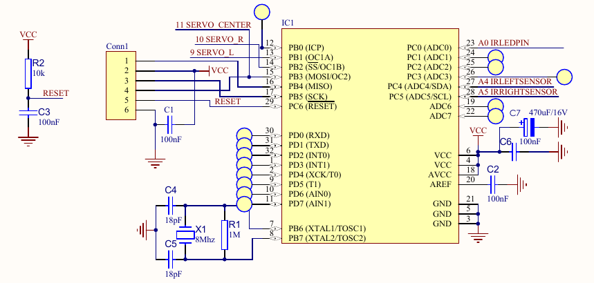 @@ -59,7 +56,6 @@ I recommend soldering the bare minimum to power up the processor, and to flash i ### The proximity sensor - Penny has two eyes, each one is composed of an infrared LED and a corresponding phototransistor. The LED emits infrared light; this light propagates through the air and once it hits an object it is reflected back towards the phototransistor. If the object is close, the reflected light will be stronger than if the object is further away. @@ -95,27 +91,10 @@ If you fail to assemble the proximity sensor, or simply dislike it, there are pl * You can buy Sharp GP2Y0A21YK0F distance measuring units: <br/> <img src="https://raw.githubusercontent.com/ssloy/penny/master/doc/GP2Y0A21YK0F.jpg" width="320"/> * Or a basic binary proximity sensor based on a LM393 differential comparator: <br/> <img src="https://raw.githubusercontent.com/ssloy/penny/master/doc/lm393.jpg" width="320"/> -# Wishlist -If you are a good soul willing to create a V2 of the motherboard, you are very welcome to do so. Here are the things that I'd like to be fixed/added/modified in the motherboard: -* The main thing is the on/off switch to cut off servo motors during flashing; -* Remove the crystal, internal RC should be just enough; -* Replace through-hole components by their SMD analogs; -* Replace R6 with a potentiometer to easily adjust the proximity sensor -* Propose good (small and foolproof) connectors instead of pin headers and optimize their placement; -* IR LEDs pads are very hard to reach under the center servo. The only viable option with the V1 motherboard is to solder the wires; -* Move a little bit the big capacitor. I had to incline it, otherwise the screw in center legs would destroy it; -* Add test pads easy to access with an oscilloscope; -* Add a couple of debug LEDs; -* Create good soldering points for unused ATMega8 pins for debugging and further extension. - -I guess that it would be a good idea to port the code to arduino environment for those who do not want to call avr-gcc directly. If you can do it, send me a pull request. - # Firmware explained - Penny can be programmed via arduino environment, but I find it quite obscure for such simple microcontrollers as ATMega8. Let us split the firmware comments into two parts: how to get the PWM working and how Penny plannifies her movements. ## PWM generation - The servos take a 50 Hz PWM signal; 1 ms minimum pulse width (0 deg), 2 ms maximum pulse width (90 deg). Penny has three servos, two of them are attached to a 16 bit timer (timer1), and the third one to a 8 bit timer (timer2). If I am not mistaken, arduino's Servo.h controls servomotors via software PWM, and I dislike that, therefore both timers are ticking in fast PWM mode. The microcontroller ticks at 8 MHz, and the timer1 ticks at 1 MHz (prescaler 8), and ICR1 provides the TOP value (20000), thus it restarts every 20 ms, providing a correct 50 Hz signal. OCR1A and OCR1B registers control microsecond pulse widths for the left and right servos. @@ -136,3 +115,25 @@ OCR2 = 1500/16; // center servo ## Obstacle detection + + + +# Wishlist +Any contribution is welcome! Send me your ideas; here is a list of things that I'd like to see improved: + +### software: +* Propose new strategies of obstacle detection. Current implementation is very basic and aims a good source code readability rather then WOW robot's behaviour. +* I guess that it would be a good idea to port the code to the arduino environment for those who do not want to call avr-gcc directly (or for those who are afraid of meddling with AVR registers). If you can do it, send me a pull request or fork the repository. + +### hardware: +If you are a good soul willing to create a V2 of the motherboard, you are very welcome to do so. Here are the things that I'd like to be fixed/added/modified in the motherboard: +* The main thing is the on/off switch to cut off servo motors power during flashing; +* Remove the crystal, internal RC should be just fine; +* Replace through-hole components by their SMD analogs; +* Replace R6 with a potentiometer to adjust the proximity sensor more easily; +* Propose good (small and foolproof) connectors instead of pin headers and optimize their placement; +* IR LEDs pads are very hard to reach under the center servo. The only viable option with the V1 motherboard is to solder the wires; +* Move a little bit the big capacitor. I had to incline it, otherwise the screw in center legs would destroy it; +* Add test pads easy to access with an oscilloscope; +* Add a couple of debugging LEDs; +* Create good soldering points for unused ATMega8 pins for debugging purposes and further extension. |