1
2
3
4
5
6
7
8
9
10
11
12
13
14
15
16
17
18
19
20
21
22
23
24
25
26
27
28
29
30
31
32
33
34
35
36
37
38
39
40
41
42
43
44
45
46
47
48
49
50
51
52
53
54
55
56
57
58
59
60
61
62
63
64
65
66
67
68
69
70
71
72
73
74
75
76
77
78
79
80
81
82
83
84
85
86
87
88
89
90
91
92
93
94
95
96
97
98
99
100
101
102
103
104
105
106
107
108
109
110
111
112
113
114
115
116
117
118
119
120
121
122
123
124
125
126
127
128
129
130
131
132
133
134
135
136
137
138
139
|
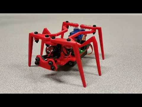
# Meet Penny#3, a 3 servo hexapod.
Penny is a low budget (roughly ten bucks) hexapod. It can be a great one-weekend project to entertain yourself and your kids. Check for Penny dancing to funky music (clickable):
[](https://youtu.be/quMe5CEoOok)
Penny avoids obstacles (clickable):
[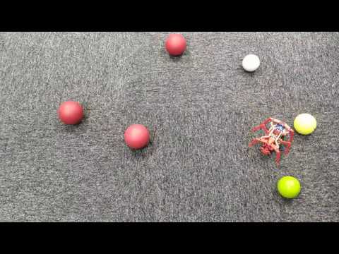](https://youtu.be/f4vZZBQZLEU)
In her current form, Penny only knows to walk; she can see (measure distance to) nearby obstacles. Her brains, however, are powerful enough to digest data from many other sensors, send me your suggestions!
Penny is a tremendous fun!
<img src="https://raw.githubusercontent.com/ssloy/penny/master/doc/A_playing_with_penny.jpg" width="512"/>
## Credits
Penny has two elder sisters, [Penny](https://youtu.be/7Py03SH5DbE) and [Penny](https://youtu.be/PiVTC8JhZTQ). Note that I have no hardware contributions, all I did is to gather the information, assemble things and write the firmware. I want this wonderful robot to be easy to clone, therefore I created this repository. The original Penny#1 is created by [Jeremy Zimmer](https://www.robotshop.com/community/robots/show/penny). The wiring being cumbersome and cheapduino being discontinued, Dennis van Elteren has designed the motherboard that I also use. Thus Penny#2 was born. Here I present you Penny#3. While I have Dennis' sanction to publish his files, I failed to contact Jeremy. The software, however is distributed under the DO WHAT THE FUCK YOU WANT TO PUBLIC LICENSE.
# How to clone
## Bill of materials
Printing the body costs next to nothing if you have a 3d printer. Here are the main things you need to build the bot:
* The motherboard. You can either etch it by yourself, or you can check chinese factories, any normal day it costs ~10€ / 10 pcs (shipping included), with discounts it can cost 2€ / 10 pcs. You can find an alternative like cheapduino or similar, because the schematics is very, very basic.
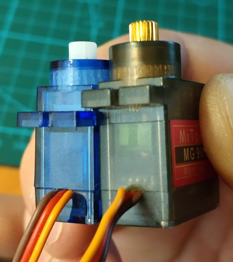
* [SG90 9G micro servo, 3 * 1.47€ / piece](https://www.aliexpress.com/item/4000595327297.html)
* [4x AAA battery holder, 1.34€ / piece](https://www.aliexpress.com/item/33049875634.html)
* [ATMega8A-AU (QFP-32), 1€ / piece](https://www.aliexpress.com/item/32557093316.html)
* [IR LED + IR phototransistor, 0.20€ / pair](https://www.aliexpress.com/item/32849824664.html)
* [Electrolytic capacitor 1000uF 16V, 0.17€ / piece](https://www.aliexpress.com/item/32954075821.html)
* [2n3904 transistor, 3 * 0.01€ / piece](https://www.aliexpress.com/item/32494899564.html)
* You will need wires, heat shrink, screws, pin headers, few 0805 resistors and capacitors. All electronic components are listed in the [hardware/motherboard/BOM.html](https://github.com/ssloy/penny/blob/master/hardware/motherboard/BOM.html) file.
**NB:** When bying 9g servos, do not forget that they come in different sizes, Penny is designed for the low profile plastic gears servos. It will work with other servos, but you might need to update SketchUp files for it. Moreover, metal gears are an overkill here.
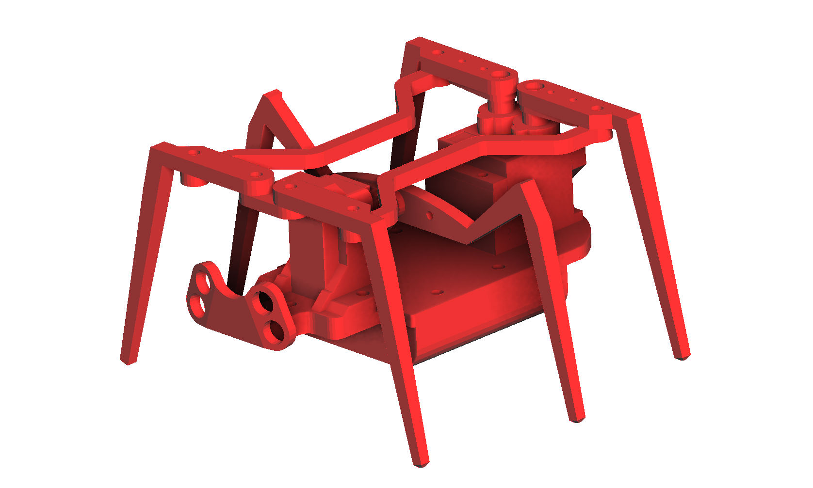
## The body
It is quite straightforward, if you have a printer, just print it. You can find the files in the [hardware/body/](https://github.com/ssloy/penny/tree/master/hardware/body) folder. All the body parts are shown here:
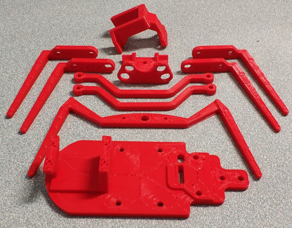
With my 1mm nozzle the prints were completed in a couple of hours. When assembled, it should look like this beast:
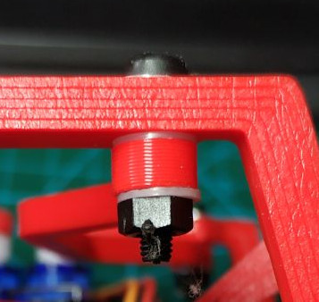
M3 nylon screws are perfect for the assembly. Use nylon washers between moving parts and lock the nut by the method of your choice.
Personally I have locked the thread with a soldering iron:
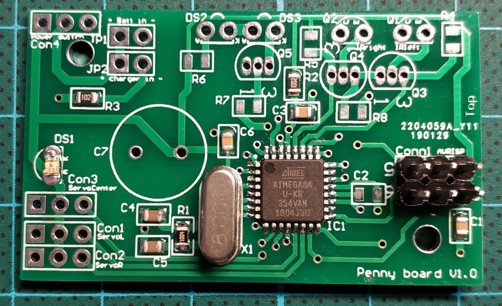
## The motherboard
The motherboard itself is pretty basic. It has an ATMega8 microcontroller and the proximity sensor circuit, nothing else. Here is the brain:
I recommend soldering the bare minimum to power up the processor, and to flash it to be sure that nothing is wrong with the fine soldering. At this stage the motherboard looks like this:
### The proximity sensor
Penny has two eyes, each one is composed of an infrared LED and a corresponding phototransistor.
The LED emits infrared light; this light propagates through the air and once it hits an object it is reflected back towards the phototransistor.
If the object is close, the reflected light will be stronger than if the object is further away.
Note that while the infrared light is not visible by a human eye, some cameras may see it and show it on the recordings,
it can be a handy tool for debugging Penny:
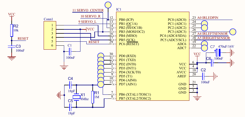
The schematics is very simple:
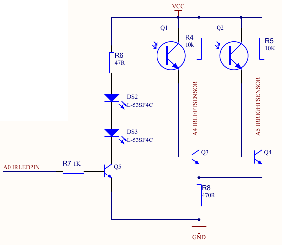
We power up two LEDs, when the phototransistors are not lit, the collector pins of Q3 and Q4 are tied to Vcc, and if the phototransistors
sense the light, the voltage on the collector pins will go down.
Here is the circuit test before I have installed it in the Penny's eyesockets:

Note that you may need to adjust the R6 resistor value.
47 Ohms provides 55mA to the LEDs; some leds might need more or less current.
For example, I have scraped a couple of LEDs from a broken toy, and they work perfectly on 3mA (910 Ohms)!
I recommend to assemble first the sensing unit on a breadboard without the LEDs.
Then light up the LED with a CR2032 or a similar battery, pand put it against the phototransistor (I do not know the internal resistance of the battery, but I have never seen a LED fried from such an operation. Correct me if I am wrong).
Verify that the voltage on the Q3 and Q4 collector pins drops as expected.
Once the sensing unit is okay, try to find a good resistor value for the LEDs to obtain the behaivour you see on the above video.
Note that it is important to put a heatshrink around both the LEDs and the phototransistors to cut off parasitic lights.
Moreover, with heatshrink it fits neatly into the eyesockets. When soldering the 2n3904, I recommend to solder first the center pin, and only then the side pins, otherwise it is too easy to create hard to remove solder bridges. Personally I find these little basterds harder to solder than the microcontroller itself (but I am bad at soldering!).
If you fail to assemble the proximity sensor, or simply dislike it, there are plenty of options:
* You can use isf471 instead of the phototransistors and all the 2n3904 circuitry.
* You can buy Sharp GP2Y0A21YK0F distance measuring units: <br/> <img src="https://raw.githubusercontent.com/ssloy/penny/master/doc/GP2Y0A21YK0F.jpg" width="320"/>
* Or a basic binary proximity sensor based on a LM393 differential comparator: <br/> <img src="https://raw.githubusercontent.com/ssloy/penny/master/doc/lm393.jpg" width="320"/>
# Firmware explained
Penny can be programmed via arduino environment, but I find it quite obscure for such simple microcontrollers as ATMega8. Let us split the firmware comments into two parts: how to get the PWM working and how Penny plannifies her movements.
## PWM generation
The servos take a 50 Hz PWM signal; 1 ms minimum pulse width (0 deg), 2 ms maximum pulse width (90 deg). Penny has three servos, two of them are attached to a 16 bit timer (timer1), and the third one to a 8 bit timer (timer2). If I am not mistaken, arduino's Servo.h controls servomotors via software PWM, and I dislike that, therefore both timers are ticking in fast PWM mode.
The microcontroller ticks at 8 MHz, and the timer1 ticks at 1 MHz (prescaler 8), and ICR1 provides the TOP value (20000), thus it restarts every 20 ms, providing a correct 50 Hz signal. OCR1A and OCR1B registers control microsecond pulse widths for the left and right servos.
The problem comes with the center servo attached to a 8 bit timer2. It does not have a handy ICR1 analog, so the overflowing frequency is controlled via the prescaler only. There are no prescalers good enough to approximate 50 Hz, here is an idea that lies somewhere inbetween a software and a hardware PWM:
* we set timer2 to tick at prescaler 128, thus it overflows after 4.096 ms = 256 * 128/(8 * 10^6).
* At the overflow we disable the timer2, so it is a one shot pulse.
* At the timer1 capture interrupt we re-arm the (one-shot) timer2.
4 ms is superior to a 2 ms max pulse width we need to control, and is well inferior to the 20 ms re-arming beat. To sum up, let us say we want to put all three servos to the middle position (1.5 ms pulse width). We need to do the following:
```c
OCR1A = 1500; // left servo
OCR1B = 1500; // right servo
OCR2 = 1500/16; // center servo
```
## Movement planner
## Obstacle detection
# Wishlist
Any contribution is welcome! Send me your ideas; here is a list of things that I'd like to see improved:
### software:
* Propose new strategies of obstacle detection. Current implementation is very basic and aims a good source code readability rather then WOW robot's behaviour.
* I guess that it would be a good idea to port the code to the arduino environment for those who do not want to call avr-gcc directly (or for those who are afraid of meddling with AVR registers). If you can do it, send me a pull request or fork the repository.
### hardware:
If you are a good soul willing to create a V2 of the motherboard, you are very welcome to do so. Here are the things that I'd like to be fixed/added/modified in the motherboard:
* The main thing is the on/off switch to cut off servo motors power during flashing;
* Remove the crystal, internal RC should be just fine;
* Replace through-hole components by their SMD analogs;
* Replace R6 with a potentiometer to adjust the proximity sensor more easily;
* Propose good (small and foolproof) connectors instead of pin headers and optimize their placement;
* IR LEDs pads are very hard to reach under the center servo. The only viable option with the V1 motherboard is to solder the wires;
* Move a little bit the big capacitor. I had to incline it, otherwise the screw in center legs would destroy it;
* Add test pads easy to access with an oscilloscope;
* Add a couple of debugging LEDs;
* Create good soldering points for unused ATMega8 pins for debugging purposes and further extension.
|
