
diff options
| author | Dmitry V. Sokolov <ha@haqr.eu> | 2020-02-19 15:39:45 +0300 |
|---|---|---|
| committer | Dmitry V. Sokolov <ha@haqr.eu> | 2020-02-19 15:39:45 +0300 |
| commit | 400551206b98ee476fc473b2dc3f98e38b86bb93 (patch) | |
| tree | c7e8c6d4cc4e18b30331e2a3c9692efdd80fc7b1 | |
| parent | b0e8a7bd7a181841ced33465d88c0636446d41c6 (diff) | |
ReadMe update
| -rw-r--r-- | README.md | 34 |
1 files changed, 34 insertions, 0 deletions
@@ -54,17 +54,51 @@ I recommend soldering the bare minimum to power up the processor, and to flash i ### The proximity sensor +Penny has two eyes, each one is composed of an infrared LED and a corresponding phototransistor. +The LED emits infrared light; this light propagates through the air and once it hits an object it is reflected back towards the phototransistor. +If the object is close, the reflected light will be stronger than if the object is further away. +Note that while the infrared light is not visible by a human eye, some cameras may see it and show it on the recordings, +it can be a handy tool for debugging Penny: +  +The schematics is very simple: + 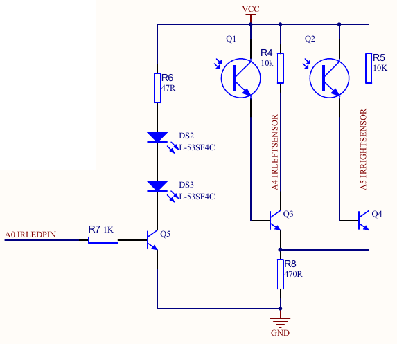 +We power up two LEDs, when the phototransistors are not lit, the collector pins of Q3 and Q4 are tied to Vcc, and if the phototransistors +sense the light, the voltage on the collector pins will go down. +Here is the circuit test before I have installed it in the Penny's eyesockets: +  +Note that you may need to adjust the R6 resistor value. +47 Ohms provides 55mA to the LEDs; some leds might need more or less current. +For example, I have scraped a couple of LEDs from a broken toy, and they work perfectly on 3mA (910 Ohms)! + +I recommend to assemble first the sensing unit on a breadboard without the LEDs. +Then take a CR2032 or a similar battery, put the LED pins on the battery directly and put it against the phototransistor. +Verify that the voltage drops as expected. +Once the sensing unit is okay, try to find a good resistor value for the LEDs to obtain the behaivour you see on the above video. +Note that it is important to put a heatshrink around both the LEDs and the phototransistors to avoid parasitic lights. +Moreover, with heatshrink it fits neatly into the eyesockets. + +If you fail to assemble the proximity sensor, or simply dislike it, there are plenty of options: + +* You can use isf471 instead of the phototransistors and all the 2n3904 circuitry. +* You can buy Sharp GP2Y0A21YK0F distance measuring units: + +<img src="https://raw.githubusercontent.com/ssloy/penny/master/doc/GP2Y0A21YK0F.jpg" width="320"/> +* Or a basic binary proximity sensor based on a LM393 differential comparator: + +<img src="https://raw.githubusercontent.com/ssloy/penny/master/doc/lm393.jpg" width="320"/> + # Wishlist If you are a good soul willing to create a V2 of the motherboard, you are very welcome to do so. Here are the things that I'd like to be fixed/added/modified in the motherboard: * The main thing is the on/off switch to cut off servo motors during flashing; * Remove the crystal, internal RC should be just enough; * Replace through-hole components by their SMD analogs; +* Replace R6 with a potentiometer to easily adjust the proximity sensor * Propose good (small and foolproof) connectors instead of pin headers and optimize their placement; * IR LEDs pads are very hard to reach under the center servo. The only viable option with the V1 motherboard is to solder the wires; * Move a little bit the big capacitor. I had to incline it, otherwise the screw in center legs would destroy it; |